

Projects: Open-access Guitar Pedal Development - Hardware
Overview
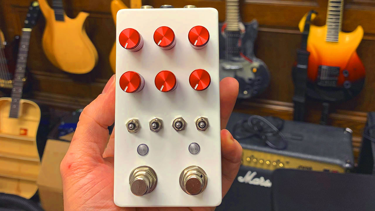
As part of our ongoing EGIL FX Kit efforts, the goal of this student project was to create a video guide to developing effects pedals. The Electric Guitar Innovation Lab (EGIL) at WPI has prepared a Digital FX Pedal Kit (described below) and a Digital FX Testing Rig to support these efforts, and, through this project and this webpage, we seek to create an open-access multimedia resource that describes how to create audio effects in a stompbox-style pedal from scratch. This guide, developed by EGIL undergraduate students in 2021, assumes the reader has no prerequisite knowledge of electronics and only the desire to learn; the kit itself uses a common set of components and other low-cost parts.
This EGIL website series was developed by students and this guide on Digital FX Pedals includes:
1) a software guide explaining how these effects can be programmed (using the Max/Gen programming language
2) this hardware guide explaining how to assemble a pedal (microcontroller, potentiometers, jacks, etc.); this guide uses hardware and software-to-hardware integration based on the work of Electro-smith and a Terrarium PCB developed by PedalPCB .
3) links to other resources for further study
This student-developed guide was commissioned by multimedia artist, composer, and friend of EGIL Steve Holec and draws from research on digital pedals supported through a grant from the Les Paul Foundation
Getting Started
-View the file repository for this project
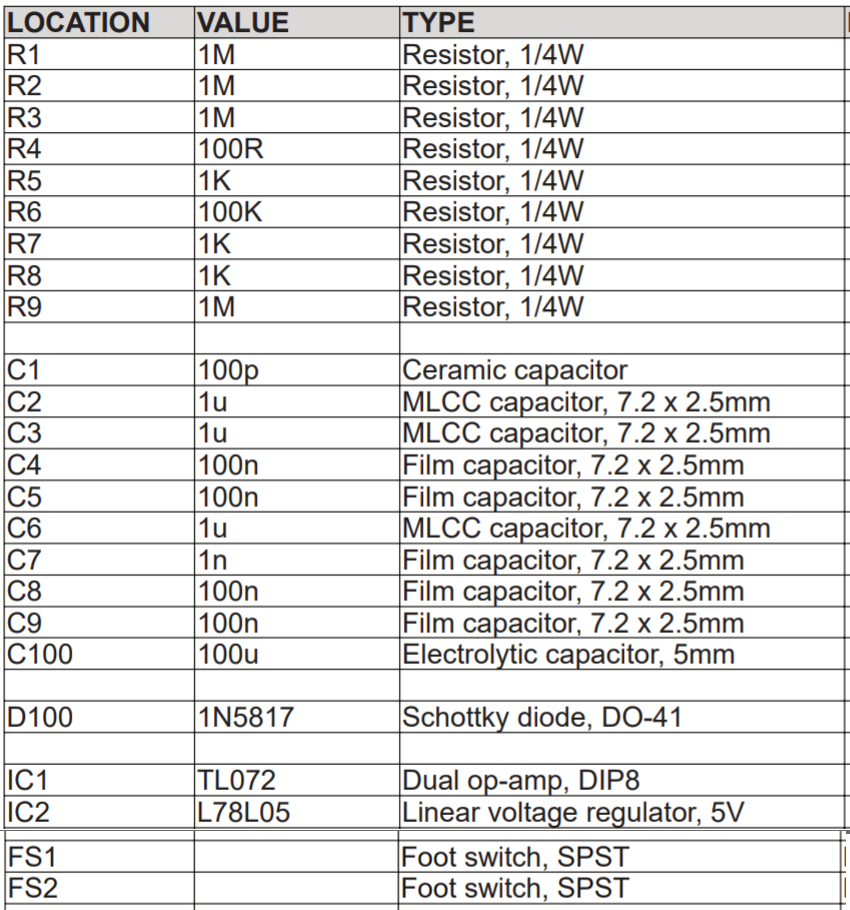
-Get all components noted in the Bill of Materials (BOM)
-Learn how to solder
-Get a soldering iron and solder
-Get access to a drill press with ⅜”, 8mm, 9/32”, ¼”, 12mm drill bits
or
-Print the 3D model enclosure
Glossary
PCB — Printed Circuit Board (bare board)
PCBA — Printed Circuit Board Assembly (with components)
Pots — Potentiometers, rotary variable resistors
IC — Integrated Chip, colloquially a “microchip”
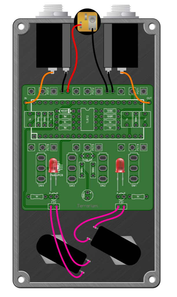 Diagram 1
Drill the Enclosure
Using the template, indent the enclosure using a punch. Drill the enclosure using the drill press. There are 5 sizes of drill bit you will need:
8mm
9/32”
¼”
12mm
 Drilling the Enclosure
Make sure to put drops of grease onto the enclosure before drilling and reapply when necessary.
Tinning
Before you begin soldering the circuit board, solder wires onto DC, Input, and Output Jacks:
➝ Tin the jacks and the wires by putting a little bit of solder on each
 Soldering
Solder the wires onto the jacks
For the input and output jacks, connect the black wires to the negatives and the blue wires to the positives as pictured above.
For the DC jack, connect the black wire to the negative and the red wire to the longer positive connector as pictured.
 Soldering
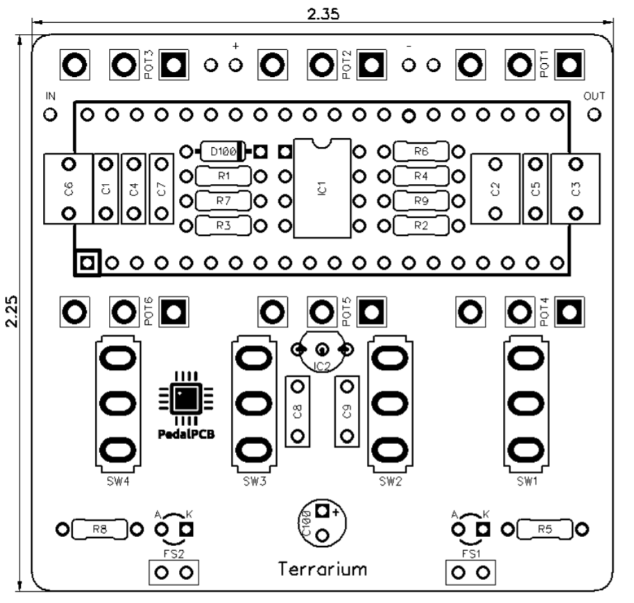
Install PCB-mount Components
Follow the diagram and its key below on PRINT side of PCB.
Cut the excess wire off of the components after soldering. Note the polarity of the 100u electrolytic capacitor, LEDs, ICs,footswitch sockets, and diode.
 PCB
PCB
 PCB
PCB

LEDs
Attach the LEDs onto the bottom side of the PCB.
 Soldering LEDs
Prep the Enclosure
➝ Prep the pots by removing all the nuts and set aside. Then, bend the leads of pots to just past square (about 85 degrees).
➝ Remove the top nut and two washers from switches, and set aside (but leave the lower nut)
➝ Remove Nuts and washers from Input & Output Jacks, and DC jack
➝ Solder wires from Input and Output Jacks to PCBA (see Diagram 1)
 Aligning pots and toggle switches to the PCBA
Install Pots and Switches
➝ To align pots and toggle switches to the PCBA, use the drilled enclosure as a jig by placing the pieces in the holes, upside down through the front of the enclosure.
Solder to the PCBA
Now that all the pieces are aligned in the holes, solder the pots and toggle switches to PCBA
 Soldering pots and toggle switches to the PCBA
DC Jack
Install the DC jack into the enclosure, and make sure to tighten the nut firmly. Then solder wires from DC jack to PCBA as shown in the first diagram.
 Installing and soldering the DC jack
PCBA in the Enclosure
Insert PCBA into the enclosure, passing pots and switches through their respective holes (it may need a bit of wiggling to get into place).
 Inserting PCBA into the enclosure
Input and Output Jacks
➝ Insert input and output jacks into position (When looking at rear of pedal, input is on the LEFT, output on the RIGHT)
➝ Add washers and nuts to Input and Output jacks to secure in place (do not tighten yet)
 Positioning the jacks
 Add mounting hardware (nuts and washers) to pots and toggles to secure PCBA in place, but do not tighten them yet.
 Install footswitches in the enclosure, add mounting hardware (do not tighten yet). Connect footswitches to the headers on the PCBA.
Finishing Up
➝ Tighten all loose nuts (Input and output jacks, Knobs, and all switches)
➝ Visually inspect all connections and tuck wires appropriately.
➝ Add knobs to potentiometer shafts, align, and use the tiny hole on the sides to tighten.
➝ Program Daisy Seed board with a patch using our Digital FX Testing Rig.
 Finishing up
 Insert LED lenses into the front of the enclosure
 Insert Daisy SEED board into headers (ensure it is in the correct orientation)
 Close up the back of the pedal enclosure
 Apply stick-on feet (if available)
Recommended Reading
To aid in future development, we recommend:
-Build Your Own Clone "How-to Info" section
-General Guitar Gadgets "How Do I Build It?" series
Project Personnel
V.J. Manzo, Founding Director and PI of the Electric Guitar Innovation Lab; PI, WPI Faculty
Ryan McKenna, WPI alumnus and Research Associate for the Electric Guitar Innovation Lab; Technical Advisor
Allie Rozear, WPI undergraduate student and co-creator of this guide
Imogen Barnes, WPI undergraduate student and co-creator of this guide
![]()
Special thanks to:
-Steve Holec for commissioning this open-access article and supporting Allie and Imogen's efforts!
-The Les Paul Foundation for supporting our ongoing research about pedals, electronics, and other areas of music technology that Les pioneered!